Circuit Bench: Build a Circuit, Change a Component, See What Changes
How long does a capacitor take to charge?
Press Run. Watch the capacitor voltage rise and the current fall. Then double the resistance and run it again.
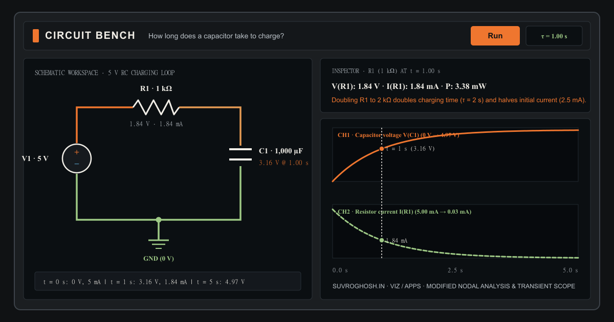
A 5 V DC supply (V1), a 1 kΩ resistor (R1), a 1,000 µF capacitor (C1, initially uncharged at 0 V), and Ground (0 V). Time constant τ = R × C = 1 second. Doubling the resistance doubles the charging time and halves the initial current.
Initialising Circuit Bench workbench…
Published · Updated
Checking article narration…
Answer a practical question with a live circuit
An equation tells you that the time constant of a resistor–capacitor circuit is . A bench instrument makes that product tangible: you see the initial current surge when the capacitor is empty, watch the current fall as the plates accumulate charge, and see what happens to the slope the moment you double the resistance.
Circuit Bench is designed around one question: what changes in this circuit when I change a component? It opens paused at on How long does a capacitor take to charge?, with a DC supply, a resistor, a capacitor initialised at , and a ground reference.
At the instant the supply is applied (), the uncharged capacitor holds its top terminal at , placing the full across and drawing an initial charging current of :
After one time constant (), the capacitor reaches approximately while the current falls to . After five seconds (), the capacitor is at —effectively charged. Select R1, turn the rotary dial or type 2k to double the resistance, and press Restart: the initial current halves to and the charging time doubles to .
Reading the workspace, inspector, and oscilloscope
Every control on the bench maps directly to a physical quantity or schematic connection:
- Predictable wiring and junctions: Click a component in the left library, place it on the snapped grid, and wire terminals either by clicking start and end terminals in sequence or by dragging. Crossing wires remain isolated unless you place an explicit junction.
- Tactile component editing: Selecting any component opens the right-hand inspector with its engineering value (
1k,4.7k,100n,10u), a logarithmic or linear rotary control with keyboard increments, and live readouts for voltage drop, branch current, and dissipated power. - Explicit measurement references: Node voltage is always measured relative to the circuit ground (). Differential voltage probes report , and every branch current reports its terminal reference direction (
A → B). - Two-channel oscilloscope: Below the schematic, two aligned trace lanes plot voltage and current against a shared time axis. Scrub the time cursor to inspect exact tabular values at any sample, switch between automatic and fixed vertical scales, or export the recorded waveform samples to CSV.
When you change a component value during a run, Circuit Bench preserves the capacitor voltages and inductor currents already stored in the circuit and marks the edit on the oscilloscope timeline. Restart resets time to and re-applies your configured initial conditions while keeping your circuit edits; Restore example returns the preset to its original schematic and values.
Eight circuits that answer concrete questions
The Examples menu in the top toolbar includes eight prepared circuits and a blank workbench:
- How long does a capacitor take to charge? — , , and starting uncharged at , demonstrating .
- Ohm’s law: What happens to current when resistance doubles? — A source across a single resistor (), showing inverse proportionality when resistance doubles to ().
- Series and parallel resistors: How does the path change the total current? — Comparing two branches in parallel across ( total) against opening an SPST switch to leave a single branch ().
- Voltage divider: How can two resistors produce a smaller voltage? — Splitting across two equal resistors to obtain a midpoint.
- Loaded voltage divider: Why does the output change when another resistor is connected? — Connecting a load in parallel with the lower leg of a divider pulls the unloaded midpoint down to ().
- Capacitor charging and discharging: What determines how quickly the voltage changes? — Using a changeover (SPDT) switch to flip an RC network between a supply and ground.
- RC low-pass filter: Why does the output shrink as the input frequency rises? — Driving a / filter () with a sine wave and comparing attenuation when the input rises to .
- RLC response: How do resistance, inductance, and capacitance affect oscillation and damping? — Observing underdamped ringing at versus critical damping at and overdamped settling at with and .
How the numerical solver works
Circuit Bench runs a deterministic Modified Nodal Analysis (MNA) engine inside a dedicated Web Worker. Ideal wires and closed switch contacts are merged into electrical nets before assembly, while voltage sources, inductors, and capacitors introduce explicit branch-current unknowns so that currents and reactive continuity are exact. Time integration uses the second-order implicit trapezoidal rule, keeping simulation sampling separate from display downsampling so a smooth oscilloscope curve never hides numerical instability.
For related interactive instruments on this site, explore the Living Systems cellular laboratory, Lens & Mirror Lab, and Between a Click and a Page.
Quick reference and FAQ
Build small circuits in your browser, change a resistor or capacitor value, press Run, and watch voltage and current respond on the schematic and two-channel oscilloscope.
Key Terms
- Time constant (τ = RC): The time for a charging capacitor to cover about 63.2% of the remaining voltage step.
- Conventional current: Flow direction from higher potential to lower potential through a passive load.
- Node voltage: Electrical potential measured at a schematic node relative to the circuit ground (0 V).
- Differential voltage: Potential difference V(A) − V(B) measured between two explicit probe points.
- Modified Nodal Analysis (MNA): Matrix formulation combining Kirchhoff's current law at nodes with branch voltage equations.
- Trapezoidal integration: Second-order implicit time-stepping method for capacitors and inductors.
Frequently asked questions
Why does the opening capacitor example start at 0 V instead of 5 V?
Circuit Bench initialises reactive components from their configured initial states rather than solving for the final DC operating point first. Starting with C1 explicitly uncharged at 0 V lets you watch the transient charging curve from the instant the 5 V supply is applied.
What happens when I turn the rotary dial while the simulation is running?
Value changes preserve the current stored capacitor voltage and inductor current, mark the parameter change directly on the oscilloscope trace, and continue the transient integration from that state.
Do the moving dots on wires show the speed of electrons?
No. Moving markers show conventional current direction and stop when current is zero. Their animation speed is scaled for visual clarity.
Why do crossing wires stay unconnected unless I add a junction?
Following standard instrumentation schematics, two wires crossing at right angles do not connect electrically unless an explicit junction dot joins them.
Word Cloud
Related reading
Selected by shared topics and section, with closer publication dates breaking ties.



Comments
Read the conversation or leave a thought for review. Comments load when this section is in view.